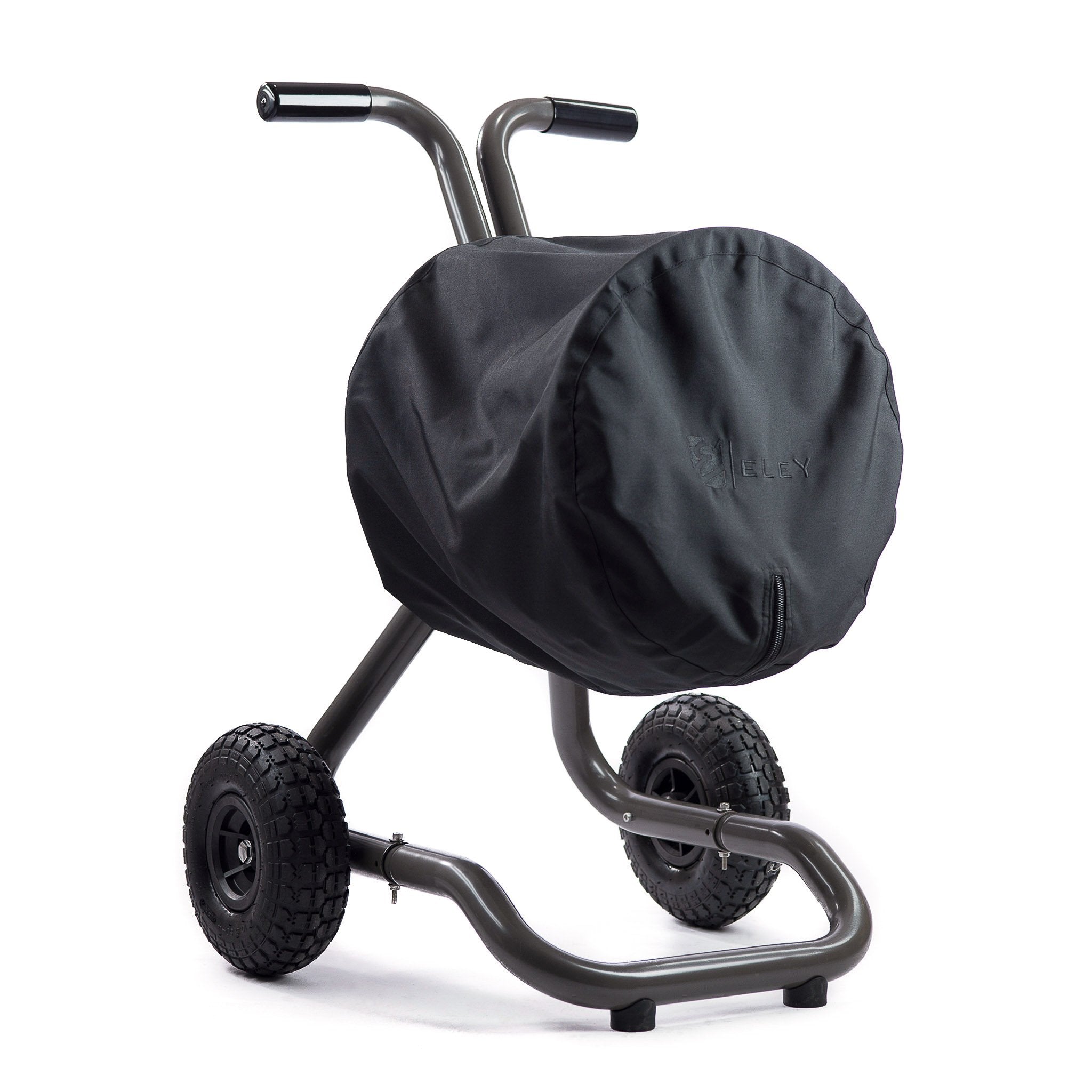

Assembly Video - Model 1043, Two-Wheel Hose Reel Cart
Assembly Video Demonstration for ELEY Model 1043
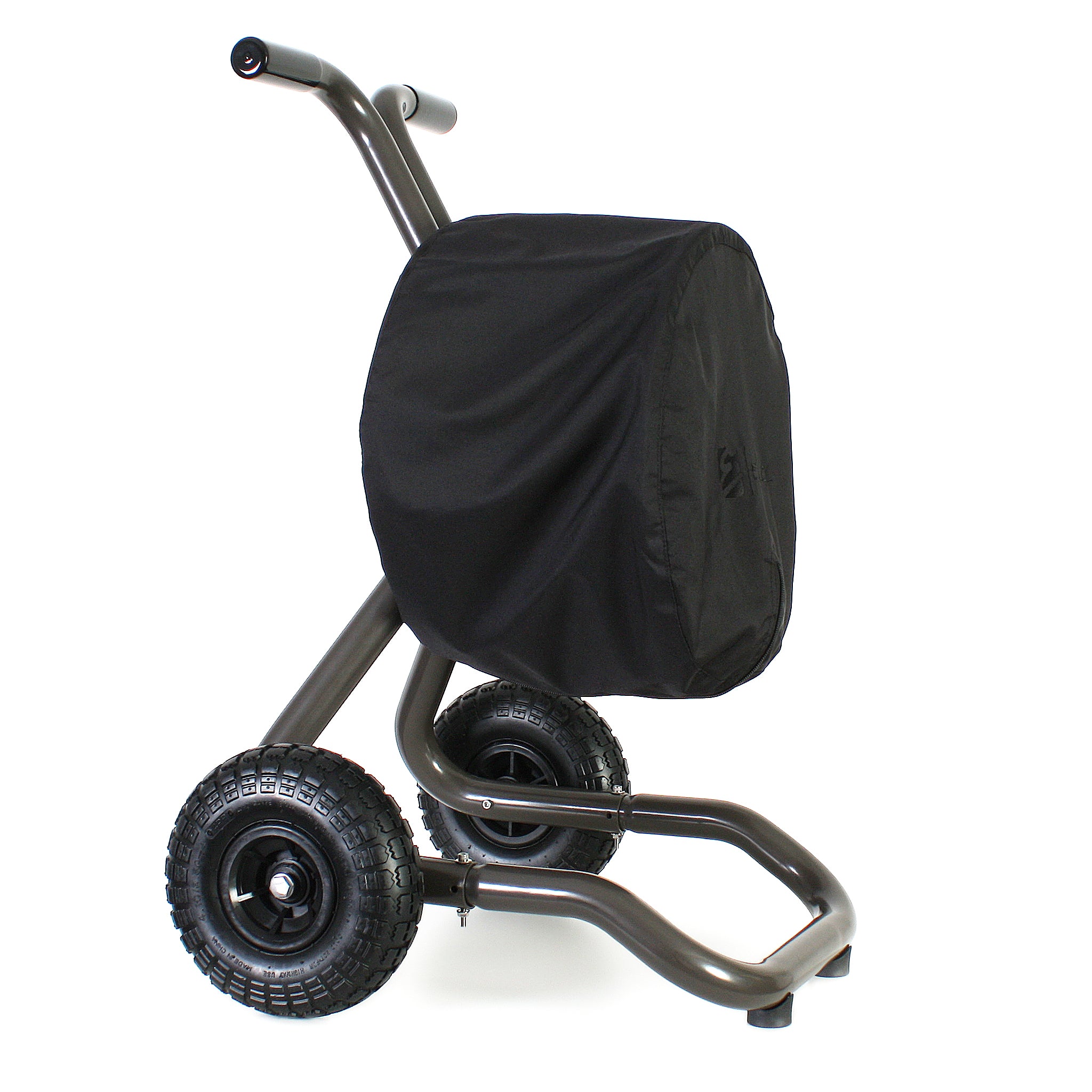
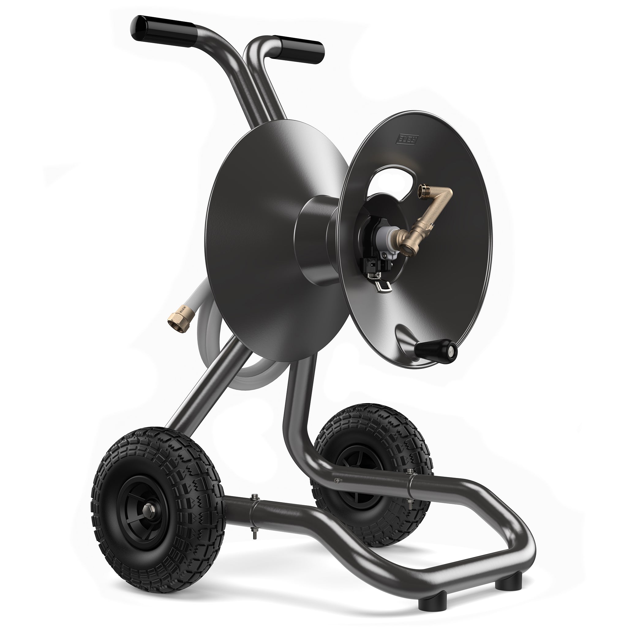
Standard Capacity - Two-Wheel Cart - Garden Hose Reel
| ⏱️ Time | Chapters | What You'll Learn |
|---|---|---|
| 0:00 | Introduction | Overview of the hose reel and the assembly process. |
| 1:00 | Connect the Flanges | Join the reel flanges together to form the reel drum. |
| 2:08 | Attach the Crank Handle | Install the crank handle used for rewinding the hose. |
| 2:53 | Attach the Tires | Install the tires onto the cart frame. |
| 4:20 | Attach the Front Bumper | Secure the front bumper assembly to the cart. |
| 6:41 | Attach the Handlebars | Install and secure the handlebars for moving the hose reel cart. |
| 7:32 | Insert the Inlet Hose & Position the Drum and Hose Strap | Route the inlet hose and place the reel drum and hose strap into position. |
| 7:44 | Install the Cam-Lever Brake | Install the brake assembly used to control reel rotation. |
| 8:00 | Attach the Inlet Hose to the Swivel | Connect the inlet hose to the reel's swivel assembly. |
| 8:50 | Attach the Garden Hose to the Reel | Connect the garden hose to the reel and prepare it for winding. |
| 10:10 | Reel the Garden Hose onto the Hose Reel | Wind the garden hose onto the drum for proper storage and operation. |
| 10:35 | Adjust the Cam-Lever Brake Tension | Set the brake tension for smooth, controlled reel movement. |
| 11:00 | How to Use the Cam-Lever Brake | Learn how to engage and release the brake during normal operation. |
| 11:22 | Closing | Final wrap-up of the assembly process. |
Assemble ELEY Garden Hose Reel Two-Wheel Cart
In this video, the manufacturer demonstrates how to assemble an ELEY hose reel two-wheel cart. The video demonstration, closed captions, and detailed instructions on this page were created to provide additional clarification during the assembly process.
If you have questions about any of our products, warranties, or guarantees, please review our helpful resources and customer service information, or use our online help desk for comprehensive 24/7/365 support.
Key Instructions and Takeaways from the Video
Introduction
Warren Eley demonstrates the assembly process for ELEY garden hose reel two-wheel carts. Every hose reel comes with a very detailed step-by-step instruction manual. For best results, lay the box down before opening, open the end, then grab the cardboard sleeve and slide the parts trays out of the box.
CONNECTING FLANGES
The front flange and back flange are held together with three screws.
- The front flange has three holes for attaching it to the back flange, a large opening for your garden hose, a rectangular opening for the hose strap assembly, and an extruded base for the crank handle.
- The back flange is a solid flange with three equidistant pre-installed nuts for attaching it to the front flange.
Instructions: Attach the front flange to the back flange by aligning the holes with the pre-installed nuts. Use the hex key wrench and start threading the screws into the back flange. Do not tighten until all three are installed, then tighten firmly.
ATTACHING THE CRANK HANDLE
The crank handle is attached to the front flange.
- Remove the pre-installed screw from the crank handle center post.
Instructions: With the front flange facing up, insert the crank handle post into the extruded base from above and insert the screw from below. Use the hex key wrench, tighten firmly.
After assembling the drum, take inventory of the parts needed to build the cart frame:
- Front bumper
- Left leg
- Right leg
- Frame Y
- Tire spindles (2)
- Push-pull handles/handlebars (2)
- 10-inch rubber tires (2)
ATTACHING THE TIRES
The same process is used to attached each tire to the right and left leg of the cart frame.
- Each leg has a large hole on one side that will face outward from the frame.
- On the opposite side, a small hole will face to the inside of the frame.
- Remove screws from tire spindles by using the hex key wrench.
Assembly Tip: Installing the tire spindle in a horizontal position will ensure the tires perform properly.
Instructions: On the concave side of the tire, insert the tire spindle in the large hole with the wedge in the horizontal position. Use the hex key wrench to tighten down firmly. Repeat this procedure to attach the second tire to the other leg, then remove the long screw from each leg.
ATTACHING THE FRONT BUMPER
The same process is used to attach each side of the front bumper using the long screws (2) that were just removed from each leg.
- Do not put the nuts on the screws after attaching the front bumper - this will be done after attaching the frame Y.
Instructions: Insert the front bumper in one of the legs, line up the vertical holes and insert the screw from the top down. Repeat the process with the other leg.
ATTACHING THE FRAME Y
The assembled legs and front bumper now attach to the frame Y to become the base of the two-wheel cart.
- Handlebar clamps (2) are rectangular.
- Leg clamps (2) are tapered with the narrow end pointing upward.
- Remove three pre-installed screws (3) and four clamps (4) before attaching the frame Y to the legs.
Assembly Tip: Use the built-in pocket on the clamps to hold the nut in place while unthreading the screw.
Instructions: Position the frame Y over the legs, then insert one of the leg screws through the frame Y and both holes in the leg. Insert the nut into the pocket of the tapered leg clamp putting the straight side of the nut into the pocket first, then finger tighten. Use the hex key wrench, but do not tighten firmly until both leg clamps are on.
Don't Forget: Now go back and put the nuts on the two screws that attach the front bumper to the legs and tighten firmly.
ATTACHING THE HANDLEBARS
Attach the handlebars to the cart frame using the rectangular clamps (2) and the screw that was removed previously.
- The handlebars are interchangeable.
- Make sure the handle faces outward from the center of the cart.
Instructions: Insert the screw through a rectangular clamp, then the handlebar, then the frame Y. Then take the other handle and slide it onto the screw. Slide the second rectangular clamp over the screw, then place the nylon insert nut straight edge first and tighten them together until the nut is inside the pocket. Keep the nut inside the pocket and use the hex key wrench to tighten firmly.
INSERTING THE HOSE & PLACING THE DRUM AND HOSE STRAP
The inlet hose will need to stay in place, fed through the axle far enough to attach to the swivel.
- Insert the hose before placing the drum or hose strap.
- Make sure the drum is pushed all the way on and the front flange is facing forward.
Instructions: Feed the male end of the hose through the axle until it just shows out the front. Next take the hose strap assembly and feed the nylon strap through the rectangular opening, pushing the assembly into place.
INSTALLING THE CAM-LEVER BRAKE
- Make sure the tab on the brake aligns with the notch in the front flange.
- Watch a separate video demonstration for additional information on adjusting and using your cam-lever brake.
ATTACHING THE HOSE TO THE SWIVEL
The inlet hose will thread into the port with the aluminum collar on the swivel.
- The swivel can be rotated in either direction to make it easier to install onto the reel.
- Make sure the O-ring gasket is in place before attaching the swivel.
Assembly Tip: Be sure to tighten the inlet hose firmly to prevent this connection from developing a leak. Use pliers to tighten more securely.
Instructions: Using a firm grip on the swivel's aluminum collar, attach it to the inlet hose. Then attach the swivel to the reel's axle. Make sure the hex head of the screw is facing up toward the opening in the front flange. Feed the hex key wrench through the opening in the flange to tighten the aluminum collar onto the axle of the reel.
Attaching the Garden Hose to the Reel
You can set up your hose reel for right-handed or left-handed rewinding. Position the stem of the swivel and feed the garden hose through the opening based on the direction you want to wind.